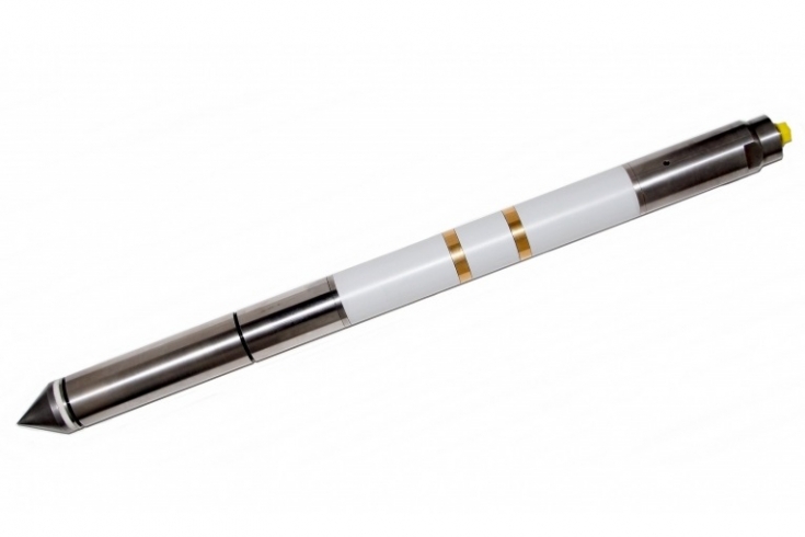
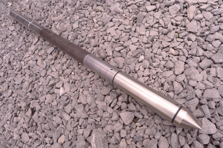
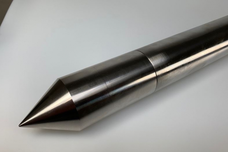
The dielectrical parameters of the soil, the electrical conductivity and the electrical permittivity vary predominantly with the soils water content and the presence of contaminations with hydrocarbons. Furthermore, electrical conductivity is inversely proportional to particle size. That is, clays usually have higher conductivity than sands. Another rule of thumb is the smaller the particle size of the soil, the lower the permeability. Thus, electrical conductivity measurements yield important lithological information and identify the locations the may be permeable and non-permeable zones. By measuring these parameters between two insulated electrodes using the soil mass as dielectric correlated with CPT results as tip resistance and local sleeve friction the contamination by hydrocarbons can be determined.
The detection limit depends on the grade of contamination and is in the order of 100 ppb in sand. Since the dielectric parameters also depend on other soil parameters, the detection limit in e.g. clayey soils are lower; correction and calibration for these soils is therefore necessary.
Unlike conventional techniques, a continuous impurity profile of the subsurface is obtained. It is possible to use these profiles to generate a three-dimensional soil model. The contaminated soil layers can easily be mapped by plotting the ration of the derivatives of the electrical conductivity and permittivity as a function of the penetration depth.
The CPT testing speed and the mobilization costs of the dielectric cone is equivalent to that of a standard CPT (piezo-)cone. This testing method thus provides in a relatively cheap way detailed information on the soil structure and on the presence and distribution of potential hydrocarbon contaminants.
Soil electrical conductivity, which is known as EC, is the ability of soil to conduct electrical current. EC is expressed in milliSiemens per meter (mS/m).
Traditionally, soil scientists used EC to measure soil salinity. However, EC measurements also have the potential for estimating variation in some of the soil physical properties in a field where soil salinity is not a problem. Recent developments in EC sensors and their ability to produce EC variation maps has attracted much attention among the geotechnical and environmental industry about potential applications of this sensor for improving field management.
Salinity is a soil property referring to the amount of soluble salt in the soil. It is generally a problem of arid and semiarid regions. Electrical conductivity (EC) is the most common measure of soil salinity and is indicative of the ability of an aqueous solution to carry an electric current.
One primary use of this dielectrical module is to locate and define preferential migration pathways for contaminants in the subsurface. It allows the user to create fast, continuous, real-time profiles of soil hydraulic properties in both fine- and coarse-grained material by measures the soil conductivity. The data can be plotted as a function of subsurface depth. This provides a representative plot of contamination levels and changes in soil permeability.
The data can be downloaded into software that creates a two- or three-dimensional interpretation of soil conductivity as a function of depth. The result is an accurate contaminant-mass-reduction estimate based on a clear picture of the subsurface mass and a lithic composition underlying your site, as well as the location of permeable and non-permeable areas. This means less time in the field, and less cost for you on a clear picture of the subsurface mass.
Since the conduction of electricity in soil takes place through the moisture-filled pores that occur between individual soil particles, the electrical conductivity of soils is determined by the following soil properties (Tom Doerge, 1999):
The greater soil porosity, the more easily electricity is conducted. Soil with high clay content has higher porosity than sandier soil. Compaction normally increases the electrical conductivity of the soil.
Dry soil is much lower in conductivity than moist soil.
Increasing concentration of electrolytes (salts) in soil water will dramatically increase the electrical conductivity of soils.
Soils containing high levels of organic matter (humus) and/or 2:1 clay minerals have a much higher ability to retain positively charged ions (such as Ca, Mg, K, Na, NH4, or H) than soils lacking these constituents. The presence of these ions in the moisture-filled soil pores will enhance the electrical conductivity of the soil in the same way that salinity does.
As temperature decreases toward the freezing point of water, the electrical conductivity of soils decreases slightly. Below freezing, soil pores become increasingly insulated from each other and the overall electrical conductivity of soils declines rapidly.
Dielectric soil properties, capacitance and electrical conductivity are governed mainly by the water content of the soil mass. By measuring these parameters between two electrodes with the soil dielectric in between, the soil moisture can thus be determined. The capacitance of dry soil is determined by its dielectric constant. For dry soil this constant is of the order of 3 to 6 and for water the constant is 80, that is, the capacitance between the two electrodes is dominated by the volume fraction of water.
In polluted soils non-aqueous phase liquids (NAPL’s), such as oil or chlorinated solvents, will replace part of the water in the soil matrix. As they do not dissolve easily in groundwater they will occur as a film of pure product, often just above the groundwater table. Dense NAPL’s such as chlorinated hydrocarbons, which are denser than water, will penetrate the groundwater table and are typically found on top of impermeable layers. These pollutants affect the dielectric properties of the soil significantly and are detectable using the Soil Moisture Probe. Soil electrical conductivity logs are used to define zones of lower conductivity, equivalent to coarser grained, more permeable sediments, which will allow the movement of contaminants (hydrocarbons, chlorinated volatile organic compounds (VOCs), or metals) in the subsurface. The lithologic information gathered with the Conductivity System can be used to aid the investigator in understanding the movement and location of contaminants in the subsurface. This information will also assist in the proper placement of monitoring or extraction wells. The combination of these parameters combined with the geomechanical measurements done by the electric CPT cone provides comprehensive information useful in determining the stratigraphy, moisture content, salt water intrusion or environmental contamination of the soil in one test. The soil moisture content is a function of the soil dielectric constant widely known as Topp’s Equation.
- Length (including S15 cone): 650 mm
- Diameter: 44 mm
- Weight: 5,100 gr
- Design: ASIC measurement electrodes with kevlar-nylon insulation
- Dielectrical constant: ranges from 1 to 80 (accuracy 0.5 % of the FS)
- Conductivity: ranges from 0 to 500 mS/m (accuracy 0.5 % of the FS)
- Soil moisture content: ranges from 0 to 100 % (accuracy 0.5 % of the FS)
- Operating temperature: 0° to +60°C
- Storage temperature: -45° to +100°C
- Connector: Lemo 10 pins (others on request)


