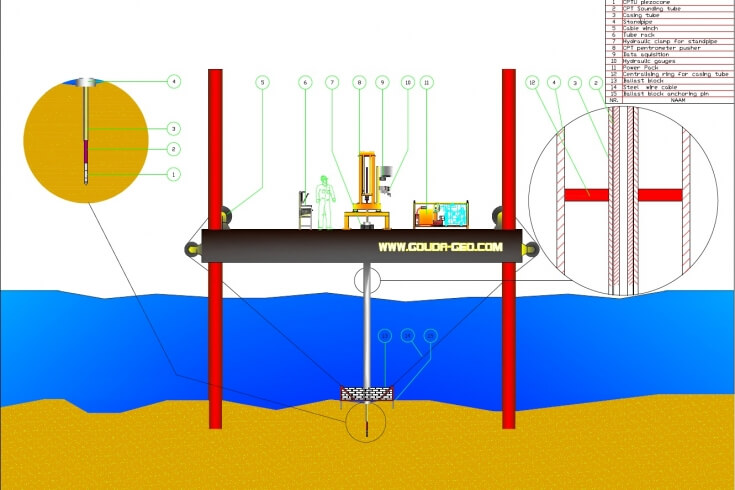
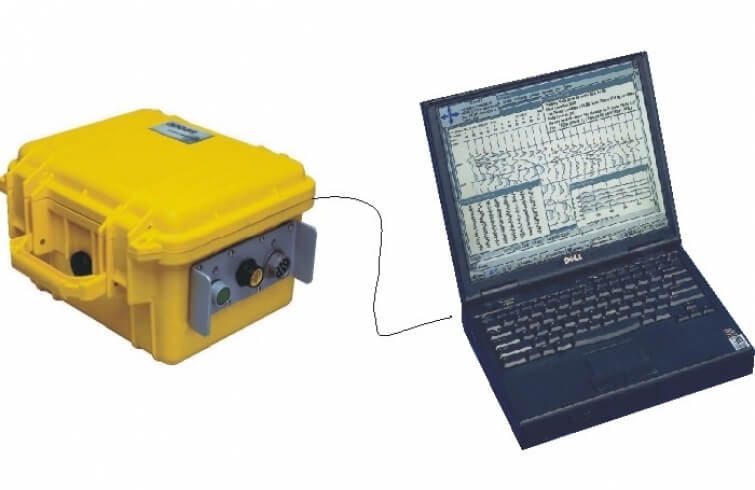
Whilst doing a Cone Penetration Test with an electric (piezo-)cone or electric measuring head quite a number of files are generated. Every single file has its own specific function. Please find underneath an inventory of all files produced and their purpose.
Interpretation of CPT Data
- Calibration File
- Header File
- Log File “0”
- Log File “1”
- Data Conversion
- Data Correction by Geotechnical Engineer
- General Exchange Format (GEF)
- CPT Graphs
- Purpose of CPT Testing
An electric CPT cone or electric measuring head is a high-precision measuring instruments designed, manufactured and tested in accordance with international standards. In order to obtain correct measuring results these instruments are calibrated and supplied with a calibration certificate and calibration file.
This calibration file is to be stored in the data acquisition software when putting the instrument in use. It contains all key reference data essential for the interpretation of obtained CPT data, such as the instrument ID, date of calibration, initial zero-points, graph scales, overload alarm values, cone area factors, and alike.
The extension of the calibration file is .cal
When beginning a CPT test, the data acquisition software asks the CPT operator to enter a number of data enabling to identify and to trace later on the specific CPT test results. The data asked are paramount for further processing of the CPT test results and it is strongly recommended to answer all questions asked carefully.
These data are stored in the header file belonging to a specific CPT test. The header file contains information on the project, such as the name of the client, the location, the job number; information on the CPT test such as the test number, date, start time, end time, ground level and pre-drill depth; and information on the measuring instrument used, such as the instrument ID, type of instrument, number of measuring channels and calibration factors.
Since the electric cone or measuring head is loaded during CPT testing, initial calibration values might shift. It is therefore compulsory to take zero-readings of each measuring channel of the instrument before and after every CPT test. The shift of the zero-readings, called the zero-shift, is also recorded in this header file and are to be taken into account when processing the CPT test results.
The extension of the header file is .0xy
xy stands for the CPT test number done in this specific project (a value ranging from 01 to 99).
Log File “0” is normally called the zero-file and contains the raw non-processed data coming from the field. It contains all measuring values recorded during the CPT test separated by a spacer bar. Every line in the log file represents the values measured after 1 cm penetration progress.
The log file comes is different formats. The CPT operator can, before starting the CPT test, select the required output format.
The extension of the zero-file is .Lxy
xy stands for the CPT test number done in this specific project (a value ranging from 01 to 99).
Log File “1” is normally called the one-file and contains the raw data coming from the field corrected for the before CPT test zero-readings of the applied measuring instrument. The lay-out is identical to that of the Log File “0”.
The extension of the one-file is .1xy
xy stands for the CPT test number done in this specific project (a value ranging from 01 to 99).
The measured values stored in above mentioned “0” and “1” log files are in count units and are to be converted into engineering parameters. The conversion of the count units in mV values is pretty straightforward; 3 count units equal 1 mV. By means of the data stored in the calibration file these mV values can be converted in the relevant engineering parameters.
Every line represents the data recorded over 1 cm depth (= 10 pulses generated by the depth
synchronisation encoder).
Every line consists of 12 different elements, i.e.:
- Element 1: represents the tip resistance (in count units)
- Element 2: represents the local sleeve friction (in count units)
- Element 3: represents the pore pressure (in count units)
- Element 4: represents the inclination (in count units)
- Element 5: represents, if attached, optional extra sensor 1 (in count units)
- Element 6: represents, if attached, optional extra sensor 2 (in count units)
- Element 7: represents, if attached, optional extra sensor 3 (in count units)
- Element 8: represents, if attached, optional extra sensor 4 (in count units)
- Element 9: represents the total number of pulses generated by the depth synchronisation encoder since the beginning of the CPT test. 10 pulses equal 1 cm penetration length.
- Element 10: represents the depth (in cm)
- Element 11: represents the time (in seconds) lapsed since the beginning of the CPT test
- Element 12: represents the time (in hundreds of seconds) lapsed since the beginning of the CPT test. So the description |41|95| for element 11 and 12 is to be red as 41,95 seconds lapsed since the beginning of the CPT test.
The actual penetration speed can be recalculated from the CPT data file. Furthermore it is possible to calculate the graph showing the penetration speed over the entire CPT test (removing the time for adding extra tubes and “smoking/talking”) from the information stored.
The raw, unprocessed data coming from the field are to be scrutinized by an experienced geotechnical engineer. All remarks made by the CPT operator stored in the header file are of paramount importance for further processing and interpretation of the CPT test results. It is up to him to filter (manually) the CPT data, removing unreliable or compromised measurements. All processing of the CPT data is solely to be done based on profound knowledge of the CPT testing procedures, the local geological conditions and the history of the job site. At this moment the raw data can be converted in the Geotechnical Exchange Format (GEF) before sharing it with other engineering, project owners, foundation experts, and alike.
The Geotechnical Exchange Format (GEF) is a general language structure for storing and transferring geotechnical information. GEF states in a procedural way how the format of the data file (rules for the storage of measurements) should be composed. GEF provides the basis for a general exchange of digital cone penetration test data. Existing formats are specifically directed at a client and therefore not unambiguous and exchangeable. In cases where large quantities of CPT data are supplied in a variety of formats, does this not only lead to communication problems but also to delays and increased costs.
There is a distinct difference between GEF and the GEF-CPT-Report. GEF is a method for the exchange of data of an arbitrary test on soil. GEF-CPT-Report is a way to exchange data of precisely one, very specific test on soil, i.e. data obtained during a Cone Penetration Test (CPT).
More detailed information on the Geotechnical Exchange Format can be found on the following website: www.dinoloket.nl.
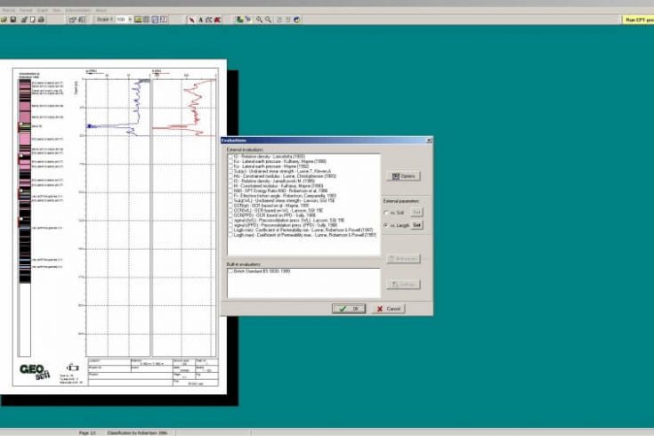
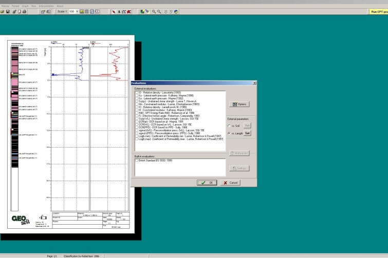
The CPT test results are visualised in so-called CPT graphs. There are generally 2 different ways of presenting the CPT test results, the Dutch type and the International type.
The Dutch CPT graph is characterised by 2 graphs displayed opposite of each other; the left graph displays the cone resistance, the local sleeve friction and, if applicable, the pore pressure. The graph on the right visualises the friction ratio and the inclination.
The International CPT graph has an individual graph for each measuring channel next to each other.
The data obtained from Cone Penetration Testing can be used for soil stability studies, the determination of the soil stratigraphy, the soils bearing capacity, the calculation of foundations, the effect of dynamic activities (e.g. traffic, large machinery) on the soil, environmental purposes, and alike.